
Introduction and Selection: ICL-16 Series and Circuit Breakers
By: Willard Wu/ Technical Dept.
willard@meanwell.com
In switching power supply (SPS) design, it is common that bulk capacitors are used to reduce ripple voltage twice the supply frequency at the output and to improve output voltage stability against power sag. However, bulk capacitors typically require a large amount of current to charge up upon initial start-up, resulting in a large inrush current. To minimize that undesired transient current, the majority of SPS designers utilize negative temperature coefficient (NTC) thermistors as a main component of the inrush current suppression circuit. The drawback is that NTC thermistors consume energy continuously while operation, not only generating heat but also having an impact on SPS’s efficiency. As a result, the resistance value of NTC thermistors cannot be too high and only can limit inrush current at a certain range, 15 - 20 times of the rated current, which some users find unacceptable. The ICL-16 series which is the exact antidote for applications that demand a low inrush current will be discussed more in the following articles.
ICL-16 Series , 16A AC Inrush Current Limiter
ICL-16 is a 16A inrush current limiter, which can be used to reduce the temporary peak current caused by capacitive loads, such as power supplies. Adding the inrush current limiter after the AC circuit breaker can effectively reduce the chance to falsely trip the AC circuit breaker when turning on AC loads, increasing the overall reliability of the system. The ICL-16 consists of three parts, i) a cement resistor “R”, which eliminates the downside of NTC thermistors that resistance decreases with increasing temperature, now inrush current can be kept at the same level at higher room temperature; ii) a bypass relay, which is used to short-circuit the “R” once its suppression job is done and is triggered by iii) a control circuit, shown in Figure1. This circuit combination significantly reduces the heat generated during operation and improves the suppression ability, thus differentiating the ICL-16 from other inrush current limiters that use NTC thermistors.
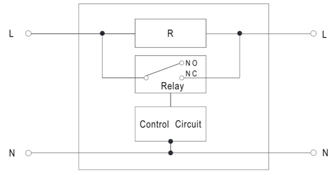 |
| Figure 1: ICL-16 block diagram |
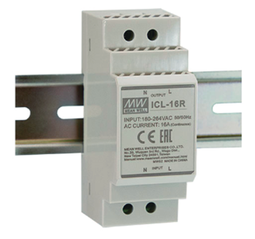
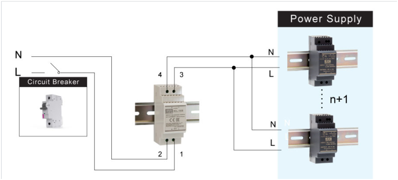
There are DIN rail type ICL-16R and linear type ICL-16L proposed to fit different applications, shown in Figure 2 and Figure 3. For detailed information, please refer to its specification on the website (https://www.meanwell.com). Figure 4 illustrates the application diagram.
 |
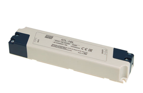 |
| Figure 2: ICL-16R | Figure 3: ICL-16L |
 |
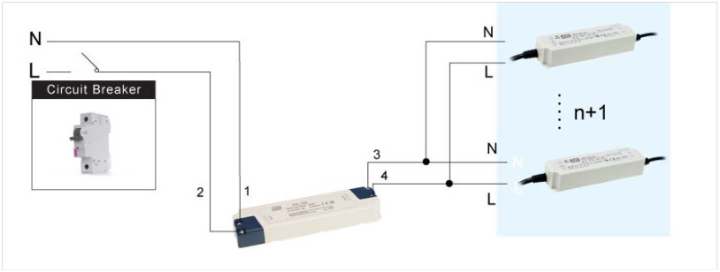 |
| Figure 4: Application diagram |
Calculation of the ICL-16 Series
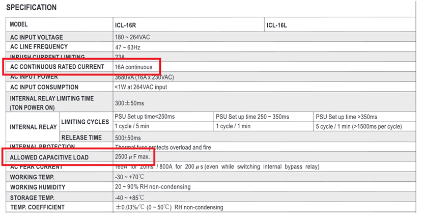
The following sections describe the calculation of the number of power supplies that can be connected to the ICL-16. According to the specification, two key parameters should be taken into consideration regarding the calculation of supplies that can be installed after the ICL-16, AC continuous rated current and allowed capacitive load. Below is an example of ICL-16R with SDR-120-24 that is to guide you through steps to manage a calculation.
STEP 1:
The specification states that AC continuous rated current: 16A; allowed capacitive load: 2500μF.
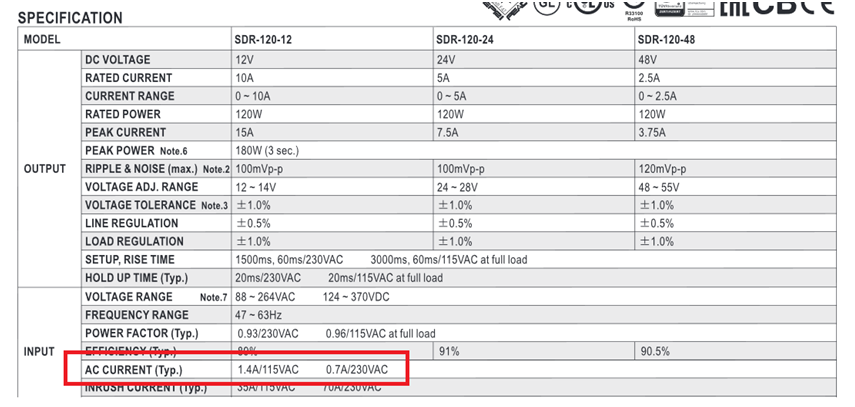
According to the specification of the SDR-120, AC current is 0.7A/230Vac at full load conditions.
There is a simple formula for calculating AC current, where AC continuous rated current of the ICL-16/ AC current of the device = 16A/ 0.7A = 22.8 → 22units (round down decimal places)
STEP 3:
According to the test report of the SDR-120 series, the capacitance of the bulk capacitor “C5” is 100μF.
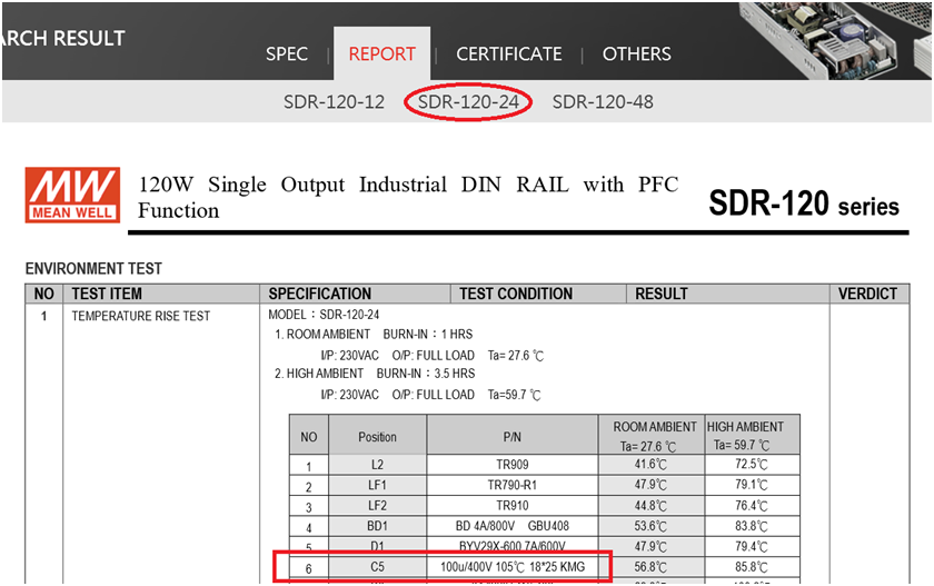
There is a formula for calculating capacitance, where allowed capacitive load of the ICL-16/ capacitance of the device = 2500μF / 100μF = 25 units (round down decimal places)
STEP 4:
Select fewer units by comparing calculated results from STEP 2 and STEP 3 then multiplied by a coefficient of 0.9 to determine a number.
22*0.9 = 19.8 → 19 units (round down decimal places)
Finally, configure a system with 19 units of SDR-120-24 and verify its reliability.
Introduction and Selection of the Circuit Breakers
The next section gives an overview on circuit breakers and the selection of a suitable circuit breaker.
(A) Introduction
A circuit breaker is an automatically operated electrical switch which is predominantly utilized as an over-current protection device to protect electrical/electronic equipment from damage caused by overload or short circuit. Its applications can be seen in many fields such as manufacturing industry, where circuit breakers are commonly used as a protective function for motors.
(B) Classification
One of the most ubiquitous circuit breakers with low rated current - i.e. rated current not more than 125 A - is the miniature circuit breaker (MCB), or being called as the no-fuse breaker (NFB) in Japan. When it comes to the instantaneous tripping current, MCBs can be split into 4 tripping characteristics: “A”, “B”, “C” and “D”. “A” is for protection of very sensitive circuits such as semiconductors. Its instantaneous tripping current is 2In to 3In (In is the rated current of a MCB). “B” is suitable for computers, electronic equipment and residential circuit protection. Its instantaneous tripping current is 3In to 5In. “C” is for general device protection in control circuits, protection of illuminating circuits with high inrush current and all other supplementary circuit protection systems. Its instantaneous tripping current is from 5In to 10In. “D” is for protection of high inrush loads like transformers, solenoid valves, etc. Its instantaneous tripping current is 10In to 20In. To operate with MEAN WELL power supplies, a MCB with a tripping characteristic “C” or “D” is recommended.
(C) Specification
Typically the following items are specified in a MCB specification.
- Rated Voltage: The input voltage the breaker designed to operate in normal condition. For example: AC 240V or 120V.
- Number of Poles: The number of circuitries the breaker can operate on at one time. For example, a 2-pole, or 2P, circuit breaker can let-through or disconnect two circuitries. There are 1-pole (1P), 2-pole (2P), 3-pole (3P) and 4-pole (4P) circuit breakers; 3P and 4P breakers are often exploited in a 3-phase circuitry network.
- Rated Current (AT or In): The highest amount of current a breaker can carry indefinitely at a certain ambient temperature.
- Frame-size rating (AF): The range of the highest current-level-setting tripping unit that can fit the breaker.
- Rated Ultimate Short-circuit Breaking Capacity (Icu): The maximum amount of short-circuit current under specified range the breaker can break, such as 380V-30kA; the circuit breaker is not required to carry the rated current after the operation or test for Icu.(6) Rated Service Short-circuit Breaking Capacity (Ics): The capability of the breaker to provide normal operation after breaking the short-circuit current under specified range, such as 380V-15kA. Ics is a percentage of Icu.
- A circuit breaker is considered violating the regulation if any one of the preceding items is not exhibited in the specification.
(D) Selection Methods
When choosing a MCB for your power supply units (PSUs), you should follow the 2 rules below:
- The rated current (In) of the MCB must always be greater than the total input current of your PSUs. In general, the rated current (In) should not be less than the total input current multiplied by a coefficient of 1.25.
- The rated service short circuit breaking capacity (Ics) of the MCB must always be greater than the total inrush current of your PSUs. There is an inrush current that occurs during the initial start-up. Typically, the duration of an inrush current is very short, lasting only a few microseconds, and can be neglected. Therefore, as long as the total inrush current does not exceed the rated service short circuit breaking capacity (Ics), the MCB will operate properly without being damaged.
Example: If a BHA32C16 MCB by SHIHLIN ELECTRIC is chosen for a system using HLP-80H LED power supplies. BHA32C16: tripping characteristic: "C" (5 times In), rated voltage: 380Vac, rated current: 16A, rated service short circuit breaking capacity (Ics): 6KA/380Vac. HLP-80H: inrush current: 70A/230Vac, input current: 0.425A/230Vac. How many units of these LED power supplies can the MCB withstand without tripping?
- 16/1.25 = 12.8; 12.8/0.425 = 30 (units)
- 70*30 = 2100A<6kA
According to the calculation above, there are 30 units of the HLP-80H that can be installed in the system. In fact, we did the aforementioned arrangement and the MCB remained closed after being turned on. If you do a calculation without a coefficient of 1.25, the units that can be used in the system are 37. However, the result we found is that the MCB was tripped by connecting 36 units of the HLP-80H to the system. In addition, the data mentioned above is based on a 25°C environment. If your system is used in a higher ambient temperature location, please refer to the ambient temperature correction curve of your MCB to de-rate the rated current (In) of the MCB.
(E) Conclusion
A suitable miniature circuit breaker (MCB) should be considered as MEAN WELL power supplies are connected to a system. This is because an appropriate MCB can prevent systems from immediately tripping when it is turned on. If it is difficult to select one single MCB for a system with a high input current, it is suggested that divide the system into several smaller systems with a lower input current and then choose available MCBs for these smaller systems.
The aforementioned calculation is based on a general method, which does not involve inrush current. Calculating inrush current requires T50 - the time duration of the inrush current pulse at 50% of Ipeak - and proof factor (K) - the pulse duration against surge current. Yet, not every CB manufacturers can specify K factor. Therefore, this article does not mention that calculation for inrush current.
Inrush current is an inevitable phenomenon while start-up of SPS. If the current system can falsely trip the CB, it is a good choice to add ICL-16 before the system to limit the inrush current.